 to 3a) Truth table (in standard order)
3b) equation d =
OK to test with Logisim, VHDL or Verilog
to 3a) Truth table (in standard order)
3b) equation d =
OK to test with Logisim, VHDL or Verilog
[CMSC 313 Home] | [Syllabus] | [Homework] | [Project] | [Lecture Notes] | [Printable all notes] | [Files] | [NASM resource] |
    The most important item on all homework is YOUR NAME!
    Print. No readable name, no credit.
    Staple or clip pages together.
    Homework must be submitted when due.  You loose 10%, one grade,
    the first day homework is late. Then 10% each week thereafter.
    Max 50% off. A zero really hurts your average!
    Paper or EMail to squire@umbc.edu  plain text preferred
    OK if homework readable by  evince  or  libreoffice  .png .jpg .doc
    If I can not read or understand your homework, you do
    not get credit.  Type or print if your handwriting is bad.
    Homework is always due on a scheduled class day within 15 minutes
    after the start of the class.  If class is canceled then homework
    is due the next time the class meets. EMailed homework has until
    midnight the day it is due.
  EMail to  squire@umbc.edu  or turn in on paper.
       Put CS313 and HW number in subject line.
Do the following manually. Show all work similar
to the method shown in Lecture 1. It is OK to check
your own work on a computer or calculator. It is not
OK to compare to other students answers. No "matching".

  Yes, those are decimal points, hexadecimal points and
  binary points in the numbers, integer-part.fractional-part

  1. Convert hexadecimal number  1456.EF to binary
  2. Convert binary number  10101010.001101 to hexadecimal
  3. Convert decimal number  126.375 to binary  (3 bits after binary point)
  4. Convert binary number  11101111.10111 to decimal
  Draw a reasonably neat picture of the Intel X86-64 "A" registers.
  Label, as usable, AL, AH, AX, EAX, RAX.
  Write five assembly lines to put value 2 into each register.
  Just use  "mov"  register name in either upper or lower case,
  both work, a comma and 2.

  Yes, this seems to be an easy assignment, but it has been
  found to actually help because you have to write all the
  forms of register names. Yes, you can use the picture from
  class lecture on WEB, but you have to draw it, not photocopy it.

  There are many types of registers,  segment, floating point,
  MMX, control, debug, and test registers.
Write one line of legal NASM assembly language for 11 problems.
Assume reasonable declarations per previous class examples.
e.g. intarith_64.asm
e.g. testreg_64.asm
e.g. ifint_64.asm
e.g. loopint_64.asm
e.g. hello_64.asm

        section .data
a:      dq      3
b:      dq      4
        section .bss
c:      resq    1
        section .text
main:
(do not assume the values at a: and b: remain the same)

 1) add the value at label b to rcx
 2) subtract the constant 2 from rcx
 3) integer multiply by the value at label b
 4) integer divide by the value at b
 5) add the address of label c to rcx
 6) jump to the label main
 7) compare register rax to the constant 6
 8) compare register rbx to the address of label b
 9) compare register rbx to the value at label b
10) place the hexadecimal constant  1234567A into rcx
11) place the address of label b into rbx

It is OK to check your work by assembling a program with
your answers, and fixing as required. (Comment out the "jump"
instruction, you do not want to run an infinite loop.)
Do not turn in .asm file.

It is not OK to compare or match you answers with other
students, T.A. or others.
(please do not perform any minimization, be neat, be consistant)
(use only and gates, and or gates, in schematic diagrams)
_
1) Convert the equation d = ((a+b)*c)+b to
1a) a truth table
1b) a schematic diagram ("and" gates into one "or" gate)
2) Convert the truth table
a b c | d
------+--
0 0 0 | 0
0 0 1 | 1
0 1 0 | 0
0 1 1 | 1
1 0 0 | 0
1 0 1 | 0
1 1 0 | 1
1 1 1 | 1
to 2a) equation d = ( )+( )+( )+( )
2b) a schematic diagram ("and" gates into one "or" gate)
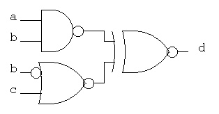
3) Convert the schematic diagram
to 3a) Truth table (in standard order)
3b) equation d =
OK to test with Logisim, VHDL or Verilog
Draw a detailed schematic of a 6-bit add and subtract circuit. The basic schematic is shown in Lecture 19 (an inverter, a mux and an adder). The more detailed schematic is:The base level schematic for fadd is:
Your schematic expands the basic schematic using six full adders, six inverters and six multiplexors. With inputs and outputs labeled and all connecting wires (signals) drawn. You do not have to put signal names on internal wires. For a more detailed schematic, you would use: You may use the left to right or top to bottom flow from the inputs a {a(5),a(4), a(3), a(2), a(1), a(0)}, b {b(5),b(4), b(3), b(2), b(1), b(0)}, and subtract to outputs s {s(5)s(4), s(3), s(2), s(1), s(0)} and cout Be neat and orderly. OK to test with Logisim, VHDL or Verilog
Compare a Karnaugh Map minimization with a Quine McClusky minimization.

The minterms are: (make this be  hw6.dat)
 0 0 0 0 0 0
 0 0 0 1 0 0
 0 1 0 0 1 0
 0 1 0 0 1 1
 0 1 0 1 1 0
 0 1 0 1 1 1
 0 1 1 0 1 0
 0 1 1 0 1 1
 0 1 1 1 1 0
 0 1 1 1 1 1
 1 1 0 1 1 0
 1 1 0 1 1 1
 1 1 1 1 1 0
 1 1 1 1 1 1
 1 0 0 0 0 0
 1 0 0 1 0 0

 cp /afs/umbc.edu/users/s/q/squire/pub/download/hw6.dat .

1) Draw the Karnaugh Map, 8 by 8, with '1' for minterm.
    Typical rows include    a=0,b=0,c=0  to  a=1,b=0,c=0
    Typical columns include d=0,e=0,f=0  to  d=1,e=0,f=0
    e.g.  0 0 0
          0 0 1  only one bit can change
          0 1 1  only one bit can change
          0 1 0  only one bit can change
          1 1 0  only one bit can change
          1 1 1  only one bit can change
          1 0 1  only one bit can change
          1 0 0  only one bit can change

Following my suggestion to use automation, whenever available,
do not bother to draw boxes. See 2)

2)  Use the Quine McClusky method to get the prime implicants (minterms)
    by use of the "qm" computer program.
    ln -s /afs/umbc.edu/users/s/q/squire/pub/download/qm  qm
    ./qm -n 6 -m -i hw6.dat -o hw6.eqn > hw6.min
    cat hw6.min
    cat hw6.eqn

Turn in 1) and  hw6.min  and  hw6.eqn

See Quine McClusky lecture notes

More information on using Quine McClusky program
A sample exam will be provided as a study guide.
No assembly language questions on the final exam.
Read the referenced sections on digital logic in the textbook.
Last updated 11/27/2019