CS411 esim tutorial
Introduction
Reserved Words
Constants
Expressions
Statements
Structure of a component definition
Main circuit structure
File structure
Truth tables for primitives
Some sample uses of primitives
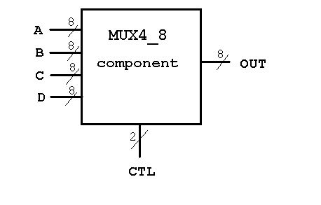
Multiplexor example component
Multiplexor example test circuit
Multiplexor Simulator control
Multiplexor example output
Multiplexor example Makefile
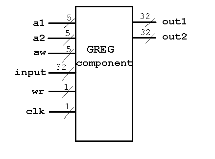
Defining a general register component
Main circuit to test general register component
Simulator control to test general register component
Simulator output of test general register component
Other Links
Esim is a structural hardware design language and simulator.

Computer architectures are built from a hierarchy of components.
Esim allows the definition of components and the use of components
in larger components.

The user prepares an esim language file that is compiled into a net list
by the  ecomp  program.  An example esim language file is shown below,
testadd4, and compiled:

	ecomp  testadd4.e  -o  testadd4.net

The simulator can be run from a  Makefile  shown below or interactively:

	esim				# the Unix command line
	esim  load  testadd4.net
        sigtrace  s			# optional, can cause much output
        esim run  100
	puts "a= [esim show -hex  a], b= [esim show -hex  b]"
	puts "sum= [esim show -hex  s], cout= [esim show cout]"

A writeup on the language, ecomp, and a writeup on the simulator control, esim, are in this WEB page,
http://www.cs.umbc.edu/~squire/  .

Simulator output can be tailored by writing Tcl/Tk code.

The basic process of designing and testing a computer architecture is the same
as designing and testing a large computer program. Do a top level design using
large components. Reduce large components to smaller components, filling in
more detail. Then build the lowest level components out of primitives. Build
higher level components out of lower level components until the program or
architecture is built. Finally execute the program or simulate the
architecture to verify it is correct.

A significant difference between conventional programming and hardware design
is the parallel nature of hardware.  All the hardware is running all the time
whereas conventional programs run sequentially one statement at a time.
A ramification of the parallel nature of hardware is that the order of
statements in a circuit does not matter.

Esim is a useful introduction into parallel programming because it is based
on several conventional programming languages yet provides parallelism and
concurrency.

A way of thinking about computer architecture is to look at a component as
a black box that has inputs, computes some functions and produces outputs.
The boxes are connected by wires that carry the signals. A basic wire or
signal can carry one bit of information that is usually a 1 or a 0 with
additional capability of X for unknown and Z for high impedance.

This brief tutorial shows some of the primitive components, samples of the
language and some results from a simulation.
after		circuits	define		else		end
falling		from		is		memory		on
otherwise	read		rising		select		signal
to		use		width		with		when
write

ns		us		ms

and		or		xor             not
#b0		#b1		#bX		#bZ
#h0FA8	#h01XZ	#hFFFFFFFF
a&b
a|b
a^b
~a
a==b
a!=b
a.b
a[upper:lower]
a when sig else b
with ctl select
         #b00: A;
         #b01: B;
         otherwise: A;
         end select
                               exp can be any expression above
a <= exp;
a <= exp on rising c;            // exp evaluated when c goes 0 to 1
a <= exp on falling c;           // exp evaluated when c goes 1 to 0
a <= exp after 3ns;		 // exp change gets into a after 3 nanoseconds
                                 // can also use other time units  7us   4ms
a <= exp on rising c after 1ns;  // combining "on ..."  "after ..."
a <= exp on falling c after 1ns; // combining "on ..."  "after ..."
signal b;
signal c17 <= #b0;
signal wrd[32] <= #hFFFFFFFF;
memory m[1024];
m read x from y when exp;	// on rising c   on falling c    after 1ns
m write x to y when exp;	// ditto
xyz use foo(a, b);
define foo(input and output signals)    // component definitions
signal aa;
signal pqr <= #b0;
circuits
    statements
end circuits;
end foo;
signal top_level;
signal clk <= #b1;
circuits
top level statements
end circuits;
zero or more component definitions
exactly one top level circuit
Esim language representation:
c<=a&b; c<=a|b; c<=a^b; b<=~a;

Truth tables
and gate or gate xor gate not
a b | c a b | c a b | c a | b
_______ _______ _______ _____
0 0 | 0 0 0 | 0 0 0 | 0 0 | 1
0 1 | 0 0 1 | 1 0 1 | 1 1 | 0
0 X | 0 0 X | X 0 X | X X | X
0 Z | 0 0 Z | X 0 Z | X Z | X
1 0 | 0 1 0 | 1 1 0 | 1
1 1 | 1 1 1 | 1 1 1 | 0
1 X | X 1 X | 1 1 X | X
1 Z | X 1 Z | 1 1 Z | X
X 0 | 0 X 0 | X X 0 | X
X 1 | X X 1 | 1 X 1 | X
X X | X X X | X X X | X
X Z | X X Z | X X Z | X
Z 0 | 0 Z 0 | X Z 0 | X
Z 1 | X Z 1 | 1 Z 1 | X
Z X | X Z X | X Z X | X
Z Z | X Z Z | X Z Z | X
Signal value definitions:
0 zero, low, false
1 one, high, true
X unknown, don't know, uninitialized
Z high impedance, not driven
c<=~a&b; d<=(a&~b&~c)|(~a&b&c);
// mux4_8 four eight bit inputs controlled by ctl to eight bit out
define mux4_8(A[8], B[8], C[8], D[8], CTL[2], OUT[8])
circuits
OUT<= with CTL
select
#b00: A;
#b01: B;
#b10: C;
#b11: D;
otherwise: A; // can't happen but need "otherwise"
end select after 1ns; // fast gates
end circuits;
end mux4_8;

// main circuit with test driving circuits
signal a[8] <= #h03;
signal b[8] <= #h0C;
signal c[8] <= #h30;
signal d[8] <= #hC0;
signal ctl[2] <= #b00;
signal out[8];
signal clk <= #b1; // part of test driver
signal ctr[2] <= #b00; // part of test driver
circuits
my_mux use mux4_8(a, b, c, d, ctl, out); // component under test
clk <= ~clk; // test driver
ctr[0] <= ~ctr[0] on falling clk after 1ns; // test driver
ctr[1] <= ~ctr[1] on falling ctr[0] after 1ns; // test driver
ctl <= ctr on rising clk after 1ns; // don't track ripples
end circuits;
esim load mux4_8.net
sigtrace out
sigtrace ctl
esim run 50
0 : out = XXXXXXXX
0 : ctl = 00
1 : out = 00000011
11 : ctl = 01
12 : out = 00001100
21 : ctl = 10
22 : out = 00110000
31 : ctl = 11
32 : out = 11000000
41 : ctl = 00
42 : out = 00000011
# Makefile for ecomp, esim circuits
#
# you can add more result files to the all: line
# then add pairs of ecomp and esim lines below
# on irix.gl machines, create the links to the executables
# ecomp and esim by typing
#
# ln -s /afs/umbc.edu/users/s/q/squire/pub/ecomp ecomp
# ln -s /afs/umbc.edu/users/s/q/squire/pub/esim esim
#
# create the above links rather than copying the files to save your disk quota
# create the links in the directory where you are doing CS411 homework
# have this Makefile in the directory
# copy the files mux4_8.e and mux4_8.run to this directory, then type make
all: mux4_8.out
mux4_8.net: mux4_8.e
ecomp mux4_8.e -o mux4_8.net
mux4_8.out: mux4_8.net mux4_8.run
esim < mux4_8.run > mux4_8.out
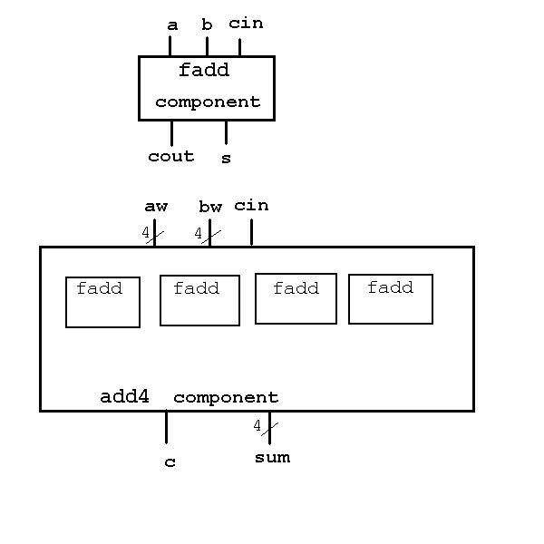
Sample input to ecomp, testadd4.e circuit
// language demonstration
// defining a component, fadd, that happens to be a full adder
define fadd(a, b, cin, s, cout)
// note parameters are by definition of type signal
// parameters may be inputs, outputs, both or unused
// in this component: a, b, cin are inputs, s and cout are outputs
circuits // note the plural! note no semicolon! closed by end circuits;
// the statements that follow are all executed in parallel
// the order of the statements means nothing to the simulation, but
// a nice ordering can make it easier to read and understand
s <= a ^ b ^ cin; // ^ is exclusive or, default update of s is 5ns
// after a change to a, b or cin
cout <= (a&b)|(a&cin)|(b&cin) after 2ns;
// & is logical and, | is logical or
// the default update delay has been replaced by 2ns
end circuits;
end fadd; // end of component fadd definition
// components can be used to build bigger components
// here is a four bit adder, add4, built from four uses of fadd
define add4(aw[4], bw[4], cin, sum[4], cout)
// aw[4] defines the parameter as being 4 bits wide
signal c[3]; // three bit temporary is needed inside this component
// in this case to pass the cout of one adder stage
// to the cin of the next adder stage
circuits
s0 use fadd(aw[0], bw[0], cin, sum[0], c[0]);
// this gives the name s0 to an instance of fadd
// aw[0] is the zeroth (first, low order) bit of the four bit signal aw
s1 use fadd(aw[1], bw[1], c[0], sum[1], c[1]);
s2 use fadd(aw[2], bw[2], c[1], sum[2], c[2]);
s3 use fadd(aw[3], bw[3], c[2], sum[3], cout);
// each instance name must be unique within a component definition
end circuits;
end add4;
// now, define the top level circuit to be simulated
// all components must be defined before they are used
// all signals must be defined before they are used
signal a[4] <= #b0101; // a[0] is 1, a[1] is zero, a[2] is one, a[3] is zero
signal b[4] <= #hF; // all bits of b are ones, h for hexadecimal, 4 bits
signal cout; // no initial value, thus value is X, unknown
signal cin <= #b0;
signal s[4];
circuits // top level of hierarchy, not enclosed in 'define'
adder use add4(a, b, cin, s, cout);
// instantiate add4 with the signal names a, b, cin, s, cout
// this in turn instantiates four copies if fadd with appropriate
// substitution of signal names
end circuits; // end of top level circuit

Sample esim control file, testadd4.run
esim load testadd4.net
sigtrace s
sigtrace cout
esim run 100
puts "a= [esim show -hex a], b= [esim show -hex b]"
puts "sum= [esim show -hex s], cout= [esim show cout]"
Also, get the file .esimrc and put it in your gl login directory
Follow instructions in Makefile to create links to ecomp and esim
Type make
Then print or view the result file, testadd4.out
0 : s = XXXX
0 : cout = X
4 : cout = 1
5 : s = XXX0
7 : s = 0XX0
7 : s = 0X00
9 : s = 0100
// greg general register set
// memory is internal, a1 address reads and outputs on out1
// a2 address reads and outputs on out2
// aw address writes input on wr & clk falling
define greg(a1[5], a2[5], aw[5], input[32], wr, clk, out1[32], out2[32])
memory mr[1024]; // 32 registers of 32 bits each
circuits
mr read out1 from a1.#b00000 when #b1; // always available
mr read out2 from a2.#b00000 when #b1;
mr write input to aw.#b00000 when wr on falling clk;
end circuits;
end greg;

signal a1[5] <= #b00010;
signal a2[5] <= #b00011;
signal aw[5] <= #b00010;
signal clk <= #b1;
signal wr <= #b1;
signal input[32] <= #hCCCCCCCC;
signal out1[32];
signal out2[32];
circuits
reg_set use greg(a1, a2, aw, input, wr, clk, out1, out2);
clk<=~clk after 10ns;
end circuits;
esim load greg.net
sigtrace out1
sigtrace out2
esim run 100
0 : out1 = XXXXXXXXXXXXXXXXXXXXXXXXXXXXXXXX Simulator Output
0 : out2 = XXXXXXXXXXXXXXXXXXXXXXXXXXXXXXXX
5 : out1 = XXXXXXXXXXXXXXXXXXXXXXXXXXXXXXX0
5 : out1 = XXXXXXXXXXXXXXXXXXXXXXXXXXXXXX00
5 : out1 = XXXXXXXXXXXXXXXXXXXXXXXXXXXXX000
5 : out1 = XXXXXXXXXXXXXXXXXXXXXXXXXXXX0000
... some lines deleted
5 : out1 = XXXXXXXX000000000000000000000000
5 : out1 = XXXXXXX0000000000000000000000000
5 : out1 = XXXXXX00000000000000000000000000
5 : out1 = XXXXX000000000000000000000000000
5 : out1 = XXXX0000000000000000000000000000
5 : out1 = XXX00000000000000000000000000000
5 : out1 = XX000000000000000000000000000000
5 : out1 = X0000000000000000000000000000000
5 : out1 = 00000000000000000000000000000000
5 : out2 = XXXXXXXXXXXXXXXXXXXXXXXXXXXXXXX0
5 : out2 = XXXXXXXXXXXXXXXXXXXXXXXXXXXXXX00
5 : out2 = XXXXXXXXXXXXXXXXXXXXXXXXXXXXX000
5 : out2 = XXXXXXXXXXXXXXXXXXXXXXXXXXXX0000
5 : out2 = XXXXXXXXXXXXXXXXXXXXXXXXXXX00000
... some lines deleted
5 : out2 = XXXXXXXXX00000000000000000000000
5 : out2 = XXXXXXXX000000000000000000000000
5 : out2 = XXXXXXX0000000000000000000000000
5 : out2 = XXXXXX00000000000000000000000000
5 : out2 = XXXXX000000000000000000000000000
5 : out2 = XXXX0000000000000000000000000000
5 : out2 = XXX00000000000000000000000000000
5 : out2 = XX000000000000000000000000000000
5 : out2 = X0000000000000000000000000000000
5 : out2 = 00000000000000000000000000000000
20 : out1 = 00000000000000000000000000000100
20 : out1 = 00000000000000000000000000001100
20 : out1 = 00000000000000000000000001001100
20 : out1 = 00000000000000000000000011001100
20 : out1 = 00000000000000000000010011001100
... some lines deleted
20 : out1 = 00000000110011001100110011001100
20 : out1 = 00000100110011001100110011001100
20 : out1 = 00001100110011001100110011001100
20 : out1 = 01001100110011001100110011001100
20 : out1 = 11001100110011001100110011001100
Note: The ripple effect within the same nanosecond time is just
showing that real electronic circuits do not change at
the exact same time. Real circuits may not change in the
sequence the simulator shows.
Last updated 8/22/00


