ART 484 - Robot Arm Parenting and Set up
This page is designed as a supplement to lectures. It is not intended to be a stand alone tutorial.
Load File
Load the file, RobotArm-Model.mb, from the pub space on the vart disk:
/afs/umbc.edu/depts/vart/pub/bailey/maya/projects/classdemos/scenes
Do not scale or translate the arm's global position. It is currently located correctly to match with scenes and objects you will load in later.
|
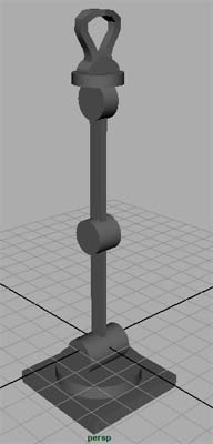
As shown at left, the model loads in a position that makes "rigging" much easier to accomplish. This position may be visually boring, but it simplies the process of parenting and creating of rotation controls.
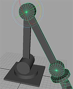
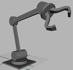
As shown at right, the robot arm is in a much more visually compelling position, but this would be very difficult to rig.
Always model and rig your objects in a neutral pose. Once rigged, the model can be quickly configured into dramatic positions. |
 |
Parenting
| Open the outliner and you will see that each object has been modeled and named. During the modeling process, pivot points were located correctly. All the geometry is clean and all the transformations have been frozen. It is ready to be "rigged" for animation. | 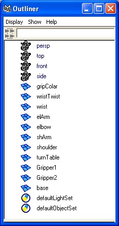 |
Creating a hierarchy can be acheived quickly in two manners: 1) Using the middle mouse button in the outliner, you can pick a node that you want to be a child and simply drag it on top of the node you want to be a parent. 2) Either in the outliner or a modeling window, you can pick the child node first, shift click to select the parent node, and then press the "p" key. (P for parent). Using this method, you can quickly select a number of children at once, select the parent last, and parent them in one step. In the example at right, the turnTable is ready to be parented to the base. |
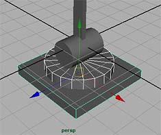 |
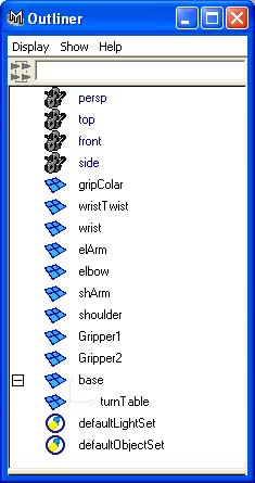
As shown in the outliner at right, the turnTable is now correctly parented to the base. Continue working up the hierarchical chain adding in the shoulder, shArm, elbow, elArm, wrist and wristTwist.
As you go, keep checking that the hierarchy is working correctly. This can be done by moving a parent to check that the child moves with it. Undo this test move ("z" key) to return the model back to its base pose. |
 |
Locking Channels and Setting Limits
As you work your way up the hierarchy, you can also take some steps to make animating easier and less prone to errors. One step is to lock all the channels of an object that will not be animated. In this example, the robot arm's joints can only rotate in one axis and will not translate or scale. The elArm and shArm never move and can be locked completely. See the following tutorial for more information:
Adding Attributes, Connection Editor, & Create Character Set
|
It can also be helpful to set limits on translations of objects so that they can not be moved beyond a certain extreme. As shown at right, the "Elbow" joint of the robot arm would not be able to rotate further then this or it would hit itself. Taking a few minutes to add in limits so that its impossible for the animator to make a mistake can save much time later. |
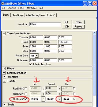 |
Setting limits is done in the Attribute Editor. Select the object, open the Attribute Editor, and open the sub-section on "Limit Information>Rotate." The center column shows the current rotation of the object. By clicking the arrows to the right and left you can set the Min and Max for rotation. Then check the boxes to turn it on. In this case, the elbow has been set with limits of plus and minus 153 degrees.
Double check your settings by rotating the elbow in your modeling window. |
Rigging the Grippers
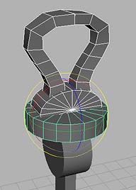
The two grippers and gripColar can be parented to the wristTwist. (The grip Colar is not animated and is simply a part of wristTwist). The model now has the correct hierarchy. |
 |
| The Outliner showing the complete hierarchy. | 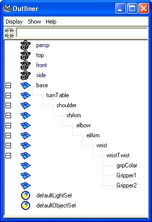 |
Animating the movement of the grippers would be very difficult at this point. They would have to be picked individually and adjusted separatly. It would be difficult to animate them symmetrically. There are a number of methods to make this easier. In this example we will drive the rotation of both grippers from the same control by taking advantage of a feature in Maya called "Driven Key". This will assure that they alway move in unison and tweaking the animation is very simple.
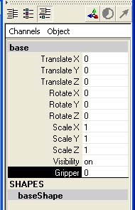 |
Add an attributeto the base node called "Gripper", make it a float and give it range from 0 (closed) to 10 (wide open). When you select the base node, this attribute should be visible. Adjusting it won't do anything because it is not yet set up to drive anything. In this case we will make this attribute "drive" the rotation of the two Grippers. For more refresher information on adding attributes:
|
 |
Next, in Maya, go to Animate>Set Driven Key>Set>Options. You will see the GUI at left. In the outliner or modeling window, select the base node and load it as the "Driver". Select its Gripper Attribute. In the modeling window or outliner, select the two grippers and load them as "Driven". In this example, they open and close by rotating on the X axis. Check that this is correct for your model, and select the appropriate rotate axis. You are now ready to set some key frames so that as the "Gripper" value changes, the rotation of both grippers changes. With the Gripper Attribute at "zero", have the grippers in the closed position and key each gripper. You have to do this separately by picking each gripper in the Driven Window and then hitting "Key".
Move the Gripper Attribute to "10" and then rotate each gripper to as wide open as you want. Make sure that they are symmetrical. Key each gripper again.
If you did this correctly, by adjusting the gripper attribute on the base, the two grippers will move.
If not, the quickest way to restart is to Delete All Channels. This deletes all keys and allows you start fresh. |
Create Controls for All Animations.
Currently to animate the arm, the animator would have to be picking each joint, adjusting it, and then setting keys. This can be painful and take much time. It would be very helpful to animate all the attributes from one location. One method for accomplishing this is to add all the needed functions to one node. This becomes a control node. In this case we will make the base of the robot arm a control.
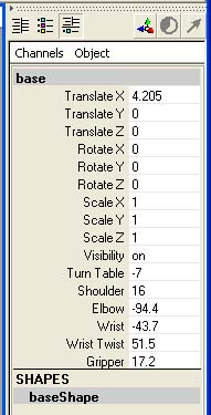
Again, add a number of attributes to the base node with names that match the joints of the arm. In this case, you do not have to put in default min and max values. Refer to the tutorial for information.
Using the Connection Editor, as indicated in the tutorial, connect the attributes to the rotation of each joint. When completed you should be able to animated the entire robot arm from this one node. |
 |
