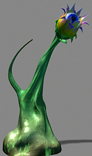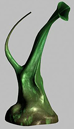

This tutorial is designed to introduce basic nurbs modeling techniques for deformation animation. An object that will be bent, twisted, squashed, or stretched as it moves, requires that it be mostly one surface. In this way, it will not tear apart at the seams as it is deformed. One tried-and-true method is to take a primitive sphere and wrangle its CVs into the final shape, but most times, a model demands more complexity then a closed sphere form and needs some appendages added. Creating a more complex unified surface usually requires attaching two surfaces together to form a new one.
For background information on creating correct surfaces and attaches, please refer to the following page:Modeling Intro and Background Information

This tutorial will go through a series of modeling techniques to build the base as shown here. You will have the opportunity to build the "head" on your own. There would be many ways to model this, but the examples shown here have been selected to offer experience in many techniques.
Typically, the modeler would probably be working from drawings or templates brought in as image planes. In this case, we will be more free-form and you can work from your own imagination.
The truck will be formed by lofting between 11 curves revolved around the Y axis. By duplicating a curve 10 times, each copy can be deformed to create any type of effect.
Draw a simple curve - something like this example - with 9-12 CVs. Pay attention to where you draw this, because it will begin the loft and will thus be a seam. It would be smart to put this seam at the "rear" of your plant. Check your options so that the curve is uniform and that the first and second CV (at the top) were snapped to the grid. This creates a flat (or tangent) surface at the top. We will eventually remove the top of the trunk to add the stem, so this is not that important in this case, but its good practive.
Duplicate the curve 10 times with a 36 degree revolution applied to the y axis. This will create all the curves for the base. Note that curve 1 and 11 are in the same location. Curve 1 will begin the loft and Curve 11 will end it. Do not change curve 1 or 11 so that the surface will blend together. We will NOT make a closed loft form. We will leave it open until a later step.
Spend some time working on the individual curves 2-10. Scale groups of CVs in or move them by hand. It is these curves that can give the appearance of folds, or the tops of roots going into the ground. Pay attention that the bottom CVs remain the same on the Y axis. This will make sure that it sits flat, or helps if you want to add on a base.
In this example I selected the top 6 CVs of every other curve and scaled them in to create folds (or a pumpkin-life surface). I then worked individually with the bottom of the curves to get some variation.
Always save your work before a major step. When saving, keep saving them with a different number at the end so that you can progress back in your modeling process. For example: Trif1.mb, Trif2.mb, Trif3.mb
When satisfied with the curves, loft between them making sure that it is a uniform open surface and that you have selected the curves in order 1-11. In this case, the curves need to be selected in order or the loft may go through curves 1 and 11.
With Construction history turned on you can continue to update the curves and watch the surface. An easy way to do this is to turn on shaded view in the perspective window, but leave the orthographic windows in wire frame. Select CVs on the curves and move them and you can see the effect on the finished surface.
When you are satisfied, save this file, delete construction history and the original curves.
Lattices are not just for animation! They make a terrific modeling tool. In this example a lattice is used to scale the trunk shape, add a twist, and to lean the top over to give room for the tentacle.
If you just delete the lattice, the model returns to its normal shape. Pick the object first and delete construction history. This deletes the lattice and leaves the trunk in its new shape.
A rough shape of the trunk is now complete. Many times you need to add additional isoparms and CVs on parts of surface so as to increase modeling detail. In this case, we will add some isoparms to the front of the trunk. (The front should be 180 degrees around from the seam)
Select the surface, go into component mode, activate the isoparm selection mask, select an existing isoparm and move it (yellow) to a location where you want more detail. You can pick V and/or U isosparms. If you use the shift key, you set multiple new isoparms. When you have positioned them where you want them, Edit Sufaces>Insert Isoparms will make them real. If you activate the CV selection mask, you will see all the new CVs that can be used to create finer detail.
Use Artisan to model the finer detail and to create a "swelled" area for the tentacle base.
Lastly, to finish the trunk, select an isoparm near the top and break the surface at that point- Edit Surfaces>Detach Surfaces. Select the top part and delete it. You should now have a hollow trunk with a hole ready for creating the stem. If there is not an isoparm on the surface where you want to make the detach, insert one exactly where you want it.
Save the file.
Select the top isoparm of the trunk and duplicate it into a real curve - Edit Curves>Duplicate Surface Curve. This creates a curve that matches exactly the shape and spans of the trunk. You will use this curve to extrude down a path to create the stem. By doing this, you will assure a smooth attach of the trunk and stem.
Set the extrude options so that the outline curve is scaled down and rotated slightly as it is extruded up the path. Depending on how you constructed the path curve, you may need to change some other extrude options to get the correct results.
With construction history, you can change the path curve to get the desired shape. When finished, delete both curves.
St this point you can attach the two surfaces. Depending on how the 2 surfaces were constructed, you may need to reverse one of them.
In component mode turn on Hulls. Pick a hull going around the top of the stem. This selects all the CVs on that isoparm. "Pick Walk" through the top rows of of CVs scaling and transforming them to create an open end for attaching a "head". You may need to add some isoparms to get the detail that you need.
At this point you can close the surface - Edit Surfaces > Open/Close Surface. This will probably create a few extra isoparms at the rear seam, but you can select 1 or 2 and delete them to decrease data and make a smoother surface.
Save your file. You can now delete all the original surfaces and any extraneous curves. Your model is only one surface at this point.
It is impossible to have a unified nurbs surface with more than 2 openings. A surface (like a piece of rolled paper) can only be made into a tube - with two openings. Many nurbs heads are made as a tube - one opening for the neck and one opening for the mouth. - it is just a very distorted tube. You can trim a hole in a surface, but it is not really an opening that a new surface can be attached to. The dilemma is how to add more appendages.
On a simplistic level, we could make the tentacle out of a cone and just stick it into the trunk. An IK deformation could be applied, but the line created by where the cone intersects the trunk would be obvious and move as the tentacle moves. It would not look like a realistic continious surface. This technique is quick and works well for some situations.
On an advanced level, there are ways of stitching surfaces together and also ways of creating animated blend shapes. These might be discussed nearer the end of the course. For this tutorial, however, we will work with an intermediate solution.
The basic shape of the tentacle will be a circle extruded down a path, but we will need a large flare at the bottom that aligns perfectly with the trunk shape. The easiest way to acheive this is to project the curve onto the surface of the trunk - creating a curve-on-surface.
Create a nurbs circle with 6-10 CVs or spans. Position this in space imagining a light source behind it projecting its image onto the surface. When you project a curve onto a surface, it will be projected from the viewpoint of the camera window you have active. In this case, you will probably have to use the perspective window.
Project the curve on the surface, Edit Surfaces>Project Curve on Surface. With Construction History on, it will be easy to move the curve after the projection and see its shape update on the trunk. Realize that you can scale and rotate the circle as well until you get a line on the trunk that makes for a good flare to the tentacle.
Select the Curve on Surface and duplicate it 3 times. Leave one where it is on the surface, but move, scale, and wrangle CVs on the other 2 curves until you have the basis for lofting the flared base. Loft a new surface.
Use the top smallest curve again as the outline for an extrude down a path to form the main tentacle shape. Attach the two surfaces together. Close them, and add some finishing touches.
Your plant is now done and should consist of only two surfaces.
To help make a smooth transition between the tentacle and trunk during animation, insert some isoparms and CVs on the trunk shape close to where the tentacle joins in. This will help keep the two surfaces remain "joined" during animation.
Create some type of "head" that sits on top of the stem. This object, most likely, will not be attached to the stem, but would be joined to an IK chain. The flare out of the stem will help cover up any problems during animation of this "joint"
OR
Create a half sphere shape and attach it to the bottom of the trunk. This, in effect, would close off one end of the "tube". This is another typical method of modeling. Pay attention to UV directions and number of spans. You might want to wrangle some CVs on the sphere to more closely match the organic shape of the base.