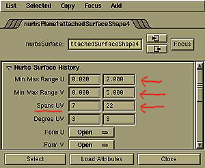
NURBS Curves and Surfaces can be constructed in two mathematical ways: chord length and uniform. Each has different attributes. Uniform curves are more straightforward and can be easily subdivided. Chord Length produces better texture mapping. For complete information on differences between Uniform and Chord Length, refer to the Maya Modeling Manual. For this tutorial it is only necessary to note that when attaching surfaces to each other, working with uniform surfaces is much more predictable.
To determine whether a surface or curve is Chord Length or Uniform, refer to the Attribute editor. Also, many times when creating a curve or surface you have a choice of creating either. When starting with a major modeling project, it is best to begin with Uniform curves at the very beginning. This is the default for CV curves.

In Chord Length Surfaces, the CVs or Isoparms are positioned along the
length of the curve in a proportional manner. The curve or surface UV starts
at the value of zero and increases to a seemingly arbitary number. In this
example the length of V is 5 and it has 22 V spans. You can tell that this
is a Chord Length Surface, because the range of U and V is not equal to
the number of spans.
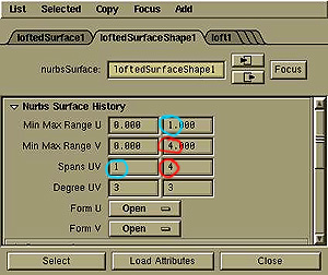
In Uniform Surfaces, the CVs or Isoparms are positioned along the length
of the curve in equal values (0, 1, 2, 3). You can tell that this is a Uniform
Surface, because the length of U and V is equal to the number of spans.
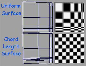
Uniform surfaces can be, however, more unpredictable when mapping textures
onto them. The following shows two similarly constructed surfaces with uneven
spaced CVs or Isoparms. The top is a Uniform surface and if the modeler
was expecting an even spaced tile floor, they would be surprised.The bottom
is a Chord length and gives a more predictable texture mapping.
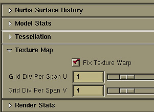 You can fix the texture mapping problem of a Uniform Surface
by turning on "Fix Texture Warp" in the Attribute Editor for the problematic
surface. Now the two different surfaces look similar when textured.

Two surfaces will attach correctly with the most predictable results when they are both uniform and have the same number of spans. Better yet, is when the isoparms between the two line up. The most frequent problem in attaching two surfaces is when the U and/or V direction is not the same between the two surfaces.
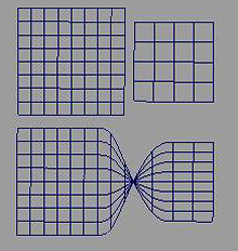
This is an example of the U or V direction being incorrect between two surfaces that will be attached. The resulting surface is "twisted". To fix this, one of the surfaces needs to be reversed. An easy way to correct this is to have History turned on, keep the incorrect attached surface, select one of the original surfaces and reverse its direction. Keep playing with the different options until the attached surface is correct.
Note. These two surfaces are the not the best for making an attached
surface. They have different number of spans, and the length is different.
It would behoove the modeler to rebuild one of the surfaces to match the
other.
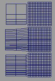
This is an example of attaching 2 different surfaces using the Multi-Knot option. The middle surface shows a "default" attach. The resultant surface is attempting to blend between the two original ones. The bottom surface was created with "Multi-Knot" turned on. This surface attempts to keep the original shapes. This is done by inserting Multiple CVs at the same location on the surface, thus allowing to have sharp angles. Multi-knots are at times the only way to resolve an attach, but they should be avoided, because they can lead to texture mapping problems and unpredictable deformations when animating.
If a modeler has to use multi-knots in a surface, they usually try to
have them in a location that will not be seen.
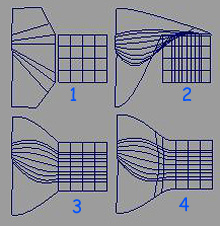
This an example of 3 different types of resultant attaches. Again, the original surfaces have been chosen for highlighting problems in attaching very different surfaces. Notice how the resultant surfaces are much different in their construction then the original surfaces. This can lead to texturing problems.
1) Original Surfaces.
2 )UV directions swapped
3) iMulti-knot attach.
4) Blend attach.
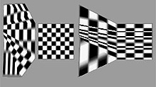
Isoparms give indications as to how textures will be mapped. In this
example the resultant attached surface is not similar to the original surfaces.
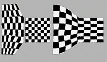
Here the textures have been "fixed" using the method explained
above. The result is more predictable, but still may not be what the modeler
intended.
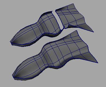
Finally, here is an example of two well constructed surfaces and the predictable attached surface that is created. Note that the two individual surfaces have the same number of spans and that the isoparms are positioned the same in each ssurface.
In most situations, when attaching surfaces, the modeler would have the two surfaces touching before the attach. These examples have been created with a large space between the two originals so that it is easy to understand the process.