Chapter 6: Staging and Steam Heating in Separation Processes.
Reasons for Staging a Separation Process
There are two main
reasons why staging is used in a separation process: (i) to amplify the
separation achieved in a single stage (an example being a distillation column)
and (ii) to increase the energy efficiency of a single stage process (an example
being a multieffect evaporator).
Cocurrent Versus Countercurrent Flow Between Stages
In a multistage
process, there are two choices concerning the flow of contacting streams: (i)
cocurrent and (ii) countercurrent. Generally, countercurrent is
advantageous since it premits a product stream to approach equilibrium with a
feed stream. In a cocurrent process, the best performance possible
corresponds to equilibrium between product streams.
Steam Heating in Separation Processes
Heat is generally
supplied to chemical processes using steam. One major reason for this is
that steam heating is a constant temperature source while, e.g., electrical
heating is a constant energy source. If fouling of the heat exchanger
surface occurs, the heating coils of an electrical heater will increase in
temperature in order to supply a constant amount of heat while the temperature
of a steam heated coil remains constant. This means that steam heating
is an inherently safer method to supply heat as compared to electrical heating.
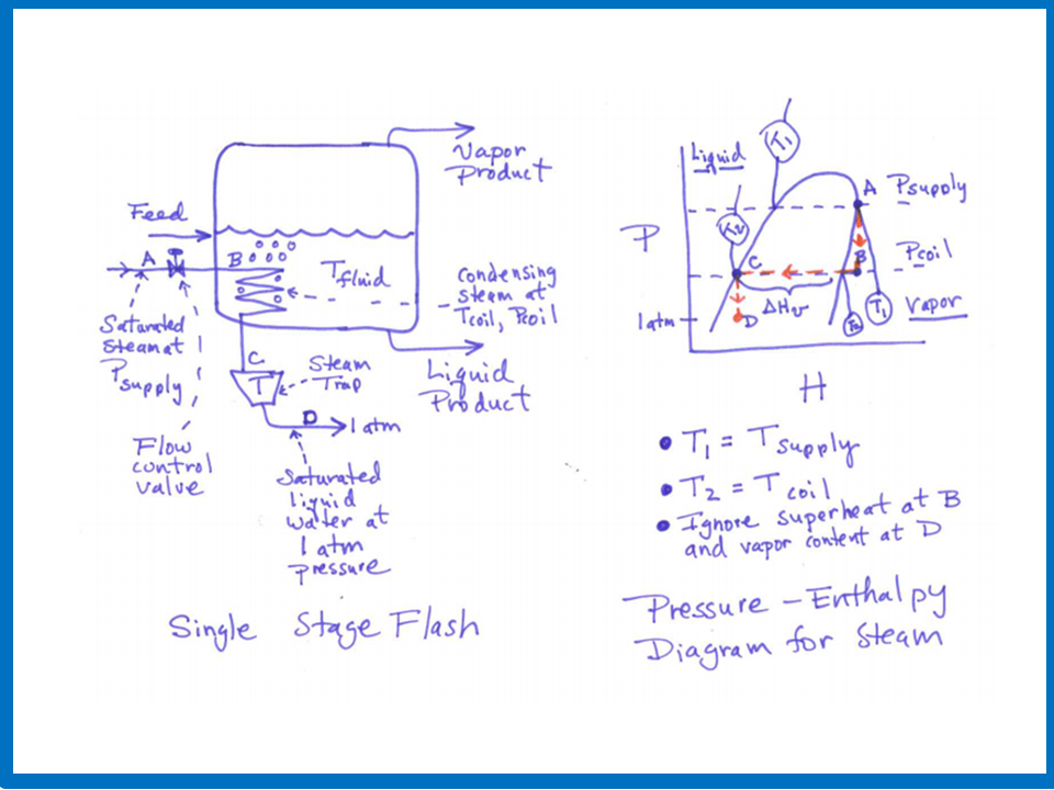
Consider the
calculation of the heat transfer rate in a steam heating system as shown in the above figure that uses a steam trap, and where steam
is condensing on the inside (the tube side) of a tubular heating coil. It is assumed that the
steam supply pressure and the temperature of the fluid to be heated on the outside (the shell side) of the heating coil are
both specified. It is also assumed that there is no pressure drop in the heating coil, but there is a pressure drop
from the steam supply pressure to the pressure
inside the heating coil across the steam flow control valve, and also a pressure drop from the pressure
inside the heating coil to the pressure at the steam trap outlet (assume to be atmospheric pressure). Finally, it is assumed that
the steam at the upstream side of the flow control valve is saturated vapor and the liquid that exits the steam trap is
saturated liquid water.
Under the conditions just described,
the temperature and pressure of the condensing steam inside the heating coil (T_coil and P_coil), the steam flow rate (f),
and the heat transfer rate (Q) can be determined by solving simultaneously the following four equations:
f = K_valve (P_supply -
P_coil)
(Relation describing the flow of steam across the control valve
in terms of the valve constant K_valve)
Q = h A (T_coil - T_fluid)
(Heat tranfer relation using a heat transfer coefficient)
T_coil =
g(P_coil)
(Equilibrium function between T and P for saturated steam)
Q = (Heat of vaporation of water) * f
(Determination of heat transfer from steam energy balance)
Additional Information: