##Chapter 8 - Distributed Systems Basics
###Introduction
In this chapter, we will cover some fundamental concepts and technologies related to the implementation of distributed systems. These concepts and technologies are typically not covered in basic networking or other core courses. The topics are:
- Caching
- Load-balancing
- Distributed naming
- Database replication
- Server virtualization
- Cloud computing
- Processes and threads
- Push technology
###Caching
Caching is an optimization for distributed systems that reduces latency and decreases network traffic. A cache transparently stores data for serving to a requestor. The typical scenario is that a requestor will always check the cache for a server first because retrieval from the cache is much faster than from the application or database directly.
There has to be some mechanism for detecting if the cache is stale (outdated information), however, and needs to be updated. Caches are evaluated by the percentage of requests that hit the cache rather than the real service and the higher the percentage, the better. The main difference between the terms buffer and cache is that a buffer is just a temporary storage location, while a cache can appear to the requestor as the original service and respond to requests. Caching occurs at all levels of computing, CPUs and disks use cache, but we will be concerned with caching that takes place on the network in the context of a distributed system. There are two categories of this kind of network-based cache:
- Web caching
- Application caching
Web caching is extremely important for performance of the web and web services and occurs at multiple levels in a system. Web caches are implemented between web servers and clients. There are four locations:
- Web browser cache
- Forward proxy cache
- Open proxy cache
- Reverse proxy cache
Web browser cache saves recent web activity in files on the client disk.
If a web browser goes to a previously viewed address, the web browser will serve the page directly from the cache rather than sending anything to the server. This clearly reduces network traffic - there is none! It also reduces latency because a disk access is faster than making a network request. Checking the freshness of the cache is done using HTTP headers and we will cover that below. Recall that images are separate files requested by the browser and can be large, so caching can give a significant performance boost by saving these files locally. Another simple example is when a user uses the back button. Rather than doing another network request, the browser uses the cache. Browser caching,
however, only works for a single client. At UMBC, for example, many users go to the same sites and it would be good to do collective caching as with a forward proxy cache.
A forward proxy cache is located at the organization (as at UMBC) or at the internet service provider (ISP). Figure 8.1 shows the structure of the forward proxy cache.
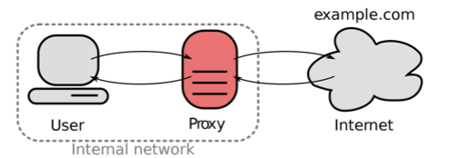
Figure 8.1. Forward proxy cache.
This kind of proxy can clearly improve on the browser cache by acting as a shared cache. As a client, my request may hit the cache even though I have never made such a request previously. Some other user on the internal network had made the previous request. A shared cache, however,
begs the question: How does the client request get routed to the cache?
There are two methods:
- Configure the browser
- Interception caching
The older method is manually configuring the web browser. This requires an administrator or a user to use a dialog box in the browser software to enter the address of the proxy. A more recent method is web proxy auto-discovery (WPAD). Netscape introduced this in the late 1990s to simplify administration of proxies. Similarly to DHCP, the web browser client would automatically check the DNS for the address of the proxy and so not require any user or administrator action. Even though this much reduced administration efforts, interception caching has become the most common method.
Interception caching uses inter-networking equipment such as routers or switches to automatically send requests to the cache. Interception proxies are sometimes called transparent proxies. Figure 8.2 shows the structure of interception caching.
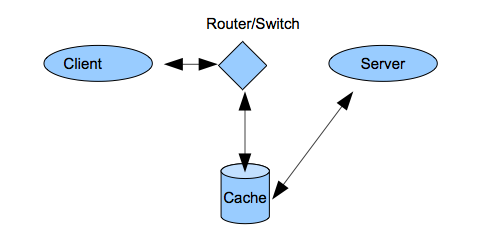
Figure 8.2. Interception caching.
The client operates as if it was connected to the server, but in reality it is connected to the cache. There is no way for a client to change this since it happens to all packets that cross the inter-networking device. This is controversial and interception caching is sometimes referred to as connection hijacking in a pejorative sense. The network performance gains that interception caching makes possible, however, has led to wide adoption. Interception caches can be placed anywhere on the network (not just for forward proxy caches). Inter-networking devices today generally operate at higher OSI layers and so can be programmed to examine packets at various layers for specific caching purposes. For example, a router that operates at layer 4 can choose to cache all packets for port 80. This will get most all web traffic, but will miss web traffic not on port 80 or any non-web traffic put on port 80 (that is uncommon). The most recent version of HTTP 1.1 shows the large influence of caching. HTTP 1.0 headers did not include a host header. In the early web, all packets were intended for the sever and so the IP address at layer 3 was sufficient. With interception caching, however,
the cache pretends to be the server and so how does the cache keep track of the real host? This is simplified if the HTTP header contains that information and so the HTTP 1.1 specification added it.
An open proxy can be anywhere on the Internet and is not associated with the client organization or that of the server. An example of an open proxy is an anonymous proxy server. This is a service that allows users to use the proxy to hide their IP address and preserve anonymity.
This is a good thing when it allows users to evade government censorship. It is a bad thing, however, when it is used criminal purposes or spamming.
A reverse proxy cache is on the internal network of the server. Figure 8.3 shows the reverse proxy cache location. They offer a faster response to the server information and reduce the load on the servers. All responses that come from the cache appear to the requestor as having come from the server. These reverse proxies can be load-balanced as we discuss later in this chapter.
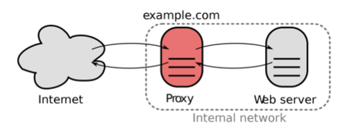
Figure 8.3. Reverse proxy cache.
The final issue for caching is freshness. We see the performance gains from caching, but how is stale information avoided? Web traffic is the most important kind of cached traffic and is controlled by the expires,
Etag, and cache-control headers in HTTP. All caches should respect these headers. Figure 8.4 shows example HTTP headers.
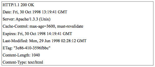
Figure 8.4. HTTP response cache-control headers.
The expires header tell how long the cache should be kept before the cache refreshes. The ETag is a short unique identifier (typically a hash function of the object content) that the server generates for each object such as a web page. It has the property that if the object changes, the ETag will also change. A cache can use the ETag to ask the server if an object has changed in a very efficient way. Cache-control headers are actually a whole class of headers and allow more detailed handling of caches. They include headers such as max-age (similar to expires and gives the the time in seconds) and must-revalidate (requires header freshness information to be strictly enforced).
A concept related to caching is a content delivery network (CDN). This improves access to data by locating content in various places on the Internet in order to get it closer to clients. This gives clients faster response times. This is commonly done for large objects that need to be downloaded by clients such as streaming data. An example would be streaming movies to clients. CDNs are typically operated as a service where a CDN company will develop a network by co-locating their servers all over the Internet at ISPs (renting space). Then a company with content contracts with the CDN provider which efficiently pushes their content to their CDN. For example, Netflix (a streaming movie service provider) has recently made a deal with Level 3 (a CDN provider) to host their streaming traffic. Other CDN providers include Akamai and Limelight. Figure 8.5 shows the structure of the CDN. The origin servers from the content provider (like Netflix) push their traffic to the distribution servers of the CDN provider (like Level 3) which pushes copies of the content to their surrogate edge servers placed all around the Internet. Now when a customer requests content, they get it from the location that offers the quickest access.
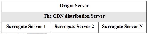
Figure 8.5. The CDN.
Application caching is caching that is managed by the application itself to improve performance rather than the web and Internet infrastructure.
Many applications now use key/value servers that can store array data (and other data structures) in memory for quick access by their users.
For example, the Redis server (http://redis.io) is an example of one of the 'noSQL' servers that are becoming popular as application caches.
Memcached (http://memcached.org/) is another example of a distributed memory object caching system for web and database applications. HTML5 offers up to 10 Mb of local application cache for javascript to use in client-side web applications.
####Load-balancing
Load-balancing is a technique to make many servers appear as one server to clients and thereby getting an increase in performance. It is a way for service providers to scale-up. The scalability is achieved by adding servers as needed to meet demand. The resulting load-balanced group of servers is called a cluster or a server farm. Load balancing offers an almost linear scalability for added servers. Web severs are easily load-
balanced because they are stateless. A request can be routed to any available server in the farm with no other considerations. This shows the power of statelessness for the design of a system.
There are three major methods of load balancing:
- Round-robin DNS (RRDNS)
- Load-balancing switches
- Application servers
RRDNS is a low cost (in fact, free!), low performance way to load-
balance. One creates a pool of servers that make up the farm and each has its own IP address. To make this cluster appear as a single server to requestors, the DNS is configured to map the same human-readable host name to the various IP addresses in the cluster using DNS A records. We cover DNS in detail in the next section. For example the DNS entries would be:
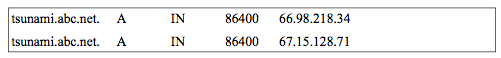
Notice that the same host name is mapped to two different IP addresses.
This is the way that DNS works by default, so when a request comes in for tsunami.abc.net, it uses the first entry and then the second one and so on until it wraps around to the first entry and begins again. The problems with this approach are: caching and lack of intelligence. An optimization for DNS is that all DNS requests are cached and so incomplete load balancing will occur with RRDNS. Lack of intelligence means that RRDNS has no method of determining when a node in a cluster is overloaded or even available, it will just result in a bad request.
The other load-balancing methods address these short-comings.
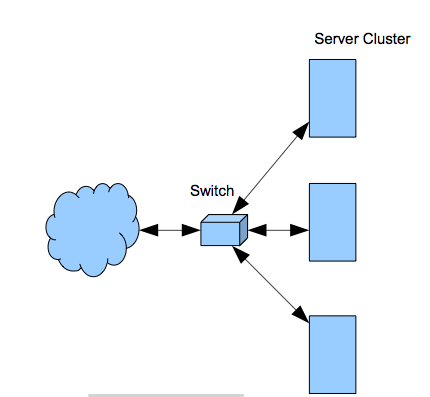
Figure 8.6. Load-balancing switch.
Load-balancing switches are the highest performance and most common method. Figure 8.6 shows the basic structure. Recall that modern switches operate at high OSI layers and so the switch can decide to load- balance based on information from any layer. Additionally, the switch can check the health of any server and so can determine if it is overloaded or down. So load-balancing switches are much more intelligent and scalable than RRDNS.
Application server load balancing approaches use the server to control the load-balancing. For example, in figure 8.6, a low cost, non-load-
balancing switch would be used to broadcast all requests to the servers.
The servers themselves would communicate with each other to decide which server picked up the request based on load and health. This is also a very scalable and intelligent method for load-balancing, but it requires a one vendor solution. For example, this is the way that Microsoft server load-balancing works. The load-balancing software is built-in to all Microsoft server operating systems.
Each of these methods works well for web servers because they are stateless. What happens with application servers that do have state?
This complicates load-balancing and there are various approaches. We will outline one here for a web server farm that is connected to an application server farm. An incoming request comes to a load-balanced stateless web server that must call a stateful application server to perform a transaction step. Figure 8.7 shows the scenario.
A request comes in to a web server and web servers can be freely load-balanced because they are stateless. So the first request comes in and is given to web server #1. This web server calls on application server #1 which can also be chosen freely by load-balancing since there is no state as of yet. The second request comes in and is load-balanced to web server #2 in the normal stateless fashion. This is the second step of a transaction, however, and so web server #2 must give the work to application server #1 because it started the transaction. How can it know since it is stateless? A common method is for all requests to use the HTTP cookie header. This header can carry any text between a client and a server. So when the client receives the response from the first step of the transaction, it sets a cookie with the name of the application server in the header. That way, the web server #2 can receive the next request and forward it to the application server #1 specified in the cookie. Although the state was put into the HTTP cookie header, no web server ever had to store any state information.
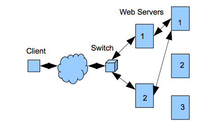
Figure 8.7. Load-balancing stateful servers.
####Distributed Naming
Naming is important for all computer-based systems to find and use resources and in a distributed system, this is complicated by the fact that the naming system must be distributed across multiple machines.
There are two major types of distributed naming systems:
- Structured naming
- Attribute-based naming
Structured naming includes NFS and DNS. Recall that we discussed the basic structure of the distributed network file system NFS in chapter 2.
The andrew file system (AFS) is more modern distributed network file system based on the earlier NFS and is used at UMBC and many universities. You have been using it on gl. You probably noticed that the complete physical path to any file in the home directory of your account follows the pattern:
`/afs/umbc.edu/users/x/y/username/home/file.txt`
where x and y are the first two letters of your username.
As with any distributed file system, data is stored on volumes, which can be physically located on any fileserver on the network. While traversing through a volume, one can hit mount points, which are references to another volume (the location may be on the same or a different server). The traversal of these mount points, and the location of file storage, is transparent to the user. For example, I have installed AFS on my home machine (a Macintosh). If I do an ls on the root of my host, I see figure 8.8. Note that afs appears as a directory in my listing, just like any other directory that is on my host but it is a mount point. I can access my home directory on gl by simply cding to it as if it were on my Macintosh, when in reality, it is at UMBC.
This is also the way that drives are mapped to your gl account on the Microsoft windows machines in the UMBC classroom labs. AFS is separate and takes priority over the local naming system (such as unix). We will do an exercise with file permissions at the end of chapter that shows this.
The domain name system (DNS) is the most widely used distributed naming system since it is used for looking up the addresses of hosts on the Internet. The DNS server is a host for each domain that keeps a database of entries about hosts under its authority called a zone file. The dig command returns information from the zone file from the controlling DNS server as in figure 8.9. Note that a default query was made for an A record. An A record maps a human-friendly host name to an IP address.
Also note that zaad.umbc.edu is actually an alias (the course syllabus is at this address). The real host name is zaad.is.umbc.edu. A CNAME record maps aliases. There are other record types that include MX (for mail servers in the domain) and NS (to indicate the authoritative name server for the domain). The dig results show there are three UMBC DNS servers at 130.85.1.3-5. You can try the dig command at the gl prompt for any host name or IP address.
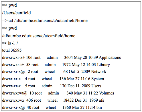
Figure 8.8. The author's machine at his house.
DNS servers do two things:
- respond to requests from programs to convert names to IP addresses (or the reverse). This means it is acting as a server.
- ask other name servers to convert names to IP addresses. This means it is acting as a client.
DNS servers also have two optimizations:
- they use caching
- they are replicated
If a DNS server ever makes a query to another name server, it saves that result in cache. That way, after some time, it rarely contacts other name servers since it has a cache of the most used mappings. DNS servers are also replicated which means that many copies of the server can exist (we discuss replication later in this chapter). A DNS resolver is the client-side of the mapping process. For example, when you enter a URL in the address box of your web browser, a local DNS resolver makes a query to the local domain's DNS server for the IP address and the DNS server responds (probably from cache). Figure 8.10 shows this process.
The DNS resolver on the DNS server operates in one of two modes:
- Recursive
- Iterative
A recursive query is one for which the DNS server will fully answer the query (or give an error) by querying other name servers as needed. An iterative query queries each DNS server as separate steps.
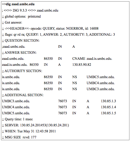
Figure 8.9. The dig command.
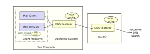
Figure 8.10. A client DNS resolver.
DNS servers are not required to support recursive queries. Figure 8.11 shows both kinds of queries where R indicates the step for a recursive query and i for the steps for an iterative one.
In the recursive case, a request is made and the server does all the required requests to resolve an address. In the iterative case, the client gets the response from each DNS server in turn and follows it up with another request. Recursive resolution has more effective caching and reduces network traffic, but increases the demand on that name server. Recall that each server maintains a cache and never makes a query if it can be resolved in cache.
All DNS servers are configured with a list of the addresses of root servers. Root servers are name servers for the top-level domains. The DNS namespace is a rooted tree where the Internet top-level domains are indicated by the file name extensions of the host names - .com, .org,
.edu, etc. These servers would obviously get a lot of traffic, but they are much replicated and so a DNS resolver contacts the closest one. We discuss replication below in the next section.
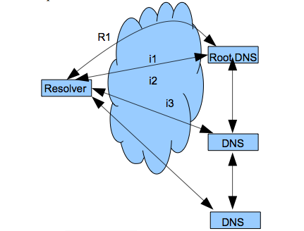
Figure 8.11. DNS resolvers.
Attribute-based naming is known as directory services. Directory services are databases of all the defined entities on a network where each entity has many attributes. Examples of directory services from vendors are Microsoft's Active Directory and eDirectory from Novell. The vendor-neutral standard for directory services is known as X.500 and most vendors or open-source implementations of directory services loosely follow this standard (with many vendor-specific differences and/or extensions).
X.500 has the following basic structure in figure 8.12. There are two protocols and two agent (server) types. The agents are directory user agent (DUA) and directory server agent (DSA). A DUA contacts a DSA in order to make a directory query. A DUA uses the directory access protocol (DAP) to make the query. Directory server agents communicate with each other using the directory system protocol (DSP). A major benefit of using directory services is that one logs into the network,
rather than to a server. In figure, 8.12 the client only contacts the single server, but has access to all resources on the network because the directory is the same on all servers. The way that it gets to be the same is by replication. We discuss replication later in this chapter.
LDAP stands for the "Lightweight Directory Access Protocol". It was originally designed to provide less complex access to X.500 databases than with DAP; however it is now more common to find LDAP servers in a standalone capacity. LDAP has become the defacto standard for Internet directory services and is also used for interoperation between directory services from different vendors.
X.500 uses a hierarchical information model for the database called the directory information tree (DIT). The rooted tree organizes all objects by node classes and each leaf node has multiple attributes. This makes it easy to find objects in the tree for response to a query.
The hierarchical path can also be used as a fully qualified identifier for an object, much like a file in a file system. For example, a tree with two branches for UMBC is shown in outline form in figure 8.13.
There are standard prefixes for the directory nodes in the DIT and we see o (organization), ou (organizational unit), and cn (common name)
which is a leaf node. So figure 8.13 shows an organization node (umbc)
with 2 branches for departments (CS and IS). The common name is one of the standard attributes defined for leaf nodes in the directory service database and there are many others such as email_address, photo, etc.
One can also create custom attributes. A fully qualified, path-like name in X.500 is called a distinguished name (DN) and would be the following for kip in figure 8.13:
`cn=kip, ou=IS, o=umbc`

Figure 8.12. X.500.
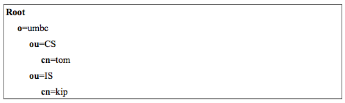
Figure 8.13. DIT.
Any network entities can be put into the directory tree such as servers,
people, printers, etc. So any user can find any entity anywhere on a very wide network with just one query to a directory service.
####Replication
Replication is the process of making copies of information on different nodes on a network and having some mechanism to ensure that consistency is maintained between the replicas. One usually wants to use replication for scalability and fault-tolerance. If there are multiple copies of information, the load on any one server is reduced and network traffic reduced by placing replicas closer to clients. Furthermore, if one of the copies goes down, there are other copies available to use.
Replication is generally needed for these reasons in a large distributed system for databases. We have already seen why this is specifically needed for the databases used in the DNS and in directory services.
Replication is typically transparent to the user and handled by the servers involved.
Replication usually involves a master/slave relationship between the original and the copies, but this can be complex. For example, when a single database is replicated, any changes to the original database (the master) are sent over the network to the copies (the slaves). This is the more simple case. The updates can take place at the same time as the change, according to some scheduling algorithm such as when the server is not busy, or in batch mode (say, at night). Multi-master replication is the more complex case and is typical of directory services replication. In this case, each directory server has master and slave partitions. The master partition is the one for which that particular server is responsible. The slave partitions are just those that are replicated from other servers. For example, in a directory service,
there may be a server at a branch office in LA and another one in an office in New York. When a user or server is added in LA, the master partition is updated and this causes replication to all other sites including New York. On the other hand, when a user is added in New York,
the slave partition in LA gets the replication update.
Multi-master systems for general purpose databases also exist, but can be very complex due to transactional conflicts that must be resolved by 2- phase commit. One simpler use of multi-master replication for databases is backup. Figure 8.14 shows how multiple databases can back each other up using multi-master replication.
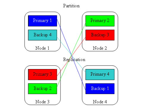
Figure 8.14. Multi-master replication for database backup.
<!-- ####CAP Theorem
Horizontal scaling of systems means that one cannot run a single server with a single database and horizontal scaling adds complexity. Data can vary across nodes in different locations, nodes can fail, and network issues create node partitions.
These concerns of consistency (C), availability (A), and partition tolerance (P) across distributed addressed by Eric Brewer's CAP Theorem. The CAP theorem states that any distributed system cannot guaranty C, A, and P simultaneously, but only in pairs. See the following descriptive reading: [CAP Theorem](http://berb.github.io/diploma-thesis/community/061_challenge.html) -->
####Processes and Threads
This is a brief discussion of processes and threads as they impact our discussion of distributed systems technology. It is not a complete treatment. A process is usually defined as a running (executing)
instance of a program. Processes will by default not share memory. The operating system creates a process table that stores all information about a process. This allows a multi-processing machine with one CPU to appear to have concurrent processing when in fact, the OS is switching the processes using preemptive multi-tasking. Multi-tasking is an expensive way to get transparent concurrency because switching out the entire process table takes time. Processes must communicate via message passing since they do not share the same address space.
Threads are lightweight sub-processes contained within a process that do not have this concurrency transparency but can be scheduled individually. Threads will by default share memory. What makes threads different from processes is that related threads share the same address space. Within one process can exist a number of threads that access common items such as global variables. Since threads share the same process state, there is much less overhead associated with swapping threads and they can communicate via memory locations.
A good example of client-side multi-threading is the web browser. A web browser is a process that makes a typical HTTP request for a web page and must get the HTML and multiple images in separate requests. To hide latencies from the user, the single process of the web browser uses a different thread for each concurrent, synchronous (blocking) request.
Another example for the web browser is event handling. A browser event loop is a thread started by the browser that is constantly scanning for and running different events such as mouse actions etc.
The main use for server-side multi-threading is that the server can create different threads to handle requests. For example, a web server such as Apache is a process that creates a new thread to serve each request. The server appears to handle many blocking requests concurrently. Additionally each thread shares the same address space as the server so communication is fast and easy (but possibly dangerous if the threads are not well behaved). Switching those threads is much faster than process switching. Web application server plug-in technologies like JVM, PHP, etc. work this way by having the web server process create new threads for each execution request rather than a whole new process (as with CGI). One problem with this model of a process that creates a new thread for each synchronous request is that it is very memory intensive and I/O (input/output) bound. There has been a recent increase of interest in asynchronous servers. These servers run as a single threaded process asynchronously. The server just runs an event loop that gets requests and passes them on to other processes.
Then a callback mechanism (we saw this on the client-side with ajax)
informs the server process when data is ready. The theory behind this is that I/O is more expensive than data processing and so the server saves time by not waiting for I/O. For example, accessing RAM may take 250 cycles while a network access may take 250 million cycles. Servers that use this model include nginx and nodejs.
Figure 8.19 shows a flow diagram for an asynchronous event loop. The event loop is: get an event, dispatch the event, and then get an event again. There are two basic events, a request for dispatch and a callback to send data back to requestor.
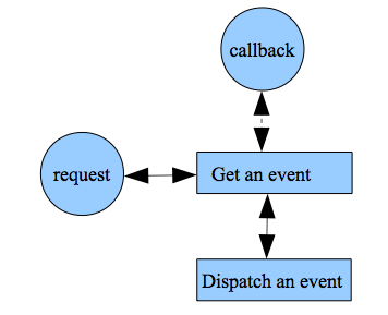
Figure 8.19. The event loop.
####Push Technology
Client/server is based on the concept of pull technology where a client always initiates a request and the server responds. There are situations, however, where we would like the server to initiate a communication to a client. One example we have already seen is publish/subscribe middleware where a server informs a client whenever a subscribed event occurs. The only way to simulate push technology in such an architecture is by (short) polling. Polling means that the client periodically (every few seconds) makes a request to check for new data. An extension of this concept is called long polling and the client opens a longer persistent connection (usually using ajax) to the server and keeps it open so that the server can send new data to the client and then the client periodically reopens the connection as needed. This kind of interaction from a web-browser to a server is sometimes called reverse-ajax and more commonly comet programming. This is a joke name coined by Alex Russell on his blog in 2006 as a play on ajax (ajax and comet are both common cleaning products). The problem with polling is that short polling has high CPU usage on the client and long polling not only has high CPU usage on the client, but increases the connections that a server must simultaneously handle and this leads to higher memory requirements.
The new HTML5 specification includes client-side websockets which eliminate the need for polling. WebSockets provides for a bi-directional, full-duplex communications channel over a TCP socket.
Recall that a socket is a combination of an IP address and a port number and so identifies an end-point for a process over a network. Websockets use a new URL protocol prefix ws://. All modern browsers support websockets, but some implementations are disabled due to security concerns that are now being addressed. For example, the javascript to create a new websocket connection is:
`var conn = new WebSocket('ws://html5rocks.websocket.org/echo');`
This technology allows the simpler creation of real-time applications like multi-player games or publish/subscribe applications. A web server or a connected client can easily send a message to all clients connected to that server with one line of code. The real-time web is a set of technologies that enable users to receive information as soon as it is published (as say RSS), rather than requesting or polling for updates.
####Microservices
The term Microservice is a relatively new term. It is a method that is used to create loosely coupled services which allows us to deploy distinct services independently while also enabling developers to develop other unique services at the same time. It allows flexibility while building multiple services. Microservices is technology independent, meaning, that it does not restrict programmers to specific technology. Since each of the applications are stored and deployed separately various applications can be tested and can be implemented independent of each other.
Various companies have started using Microservices to give themselves an advantage over their competition. Some of the big name companies that make use of Microservices are Netflix, Amazon, Ebay, Groupon, Comcast Cable, Uber, Sound Cloud, etc. Microservice gives companies flexibility deploying and introducing new features to the ever changing and demanding consumer base. While Microservices have some advantages over Monolithic applications it also has some drawbacks that have kept some companies away from adapting Microservices.
Both Microservices and Web Services are based on a similar design pattern, namely service-oriented architecture (SOA). Web Services technologies such as WSDL, SOAP and REST focus on the interaction of services. Microservices focus on internal system design, implement and deploy.
####Chapter 8 Exercises
Do the end-of-chapter exercises for each chapter of the book by following the link in the on-line syllabus.